News:

Please read the Forum Code of Conduct   >>Click Here <<

Main Menu
Menu

Show posts

This section allows you to view all posts made by this member. Note that you can only see posts made in areas you currently have access to.

Show posts Menu

Messages - jviss

#16
Large / Re: Big Hauler Version 2 vs Version 5 Annie
February 29, 2020, 09:28:33 PM
Quote from: Loco Bill Canelos on December 17, 2019, 11:46:31 PM
If using LED's be sure to add a 1000K resistor to the circuit to protect the LED.

I think you meant 1kΩ, which is 1000Ω, not 1000k, right?
#17
Just an FYI, in the topic "Repairs to the Bachmann Standard line Big Hauler 4-6-0, and Anniversary 4-6-0," which is read only and I could therefore not reply to, there's an error in George Sheyer's disassembly instructions.  On "The Bottom Side" he says to "Pry out the pilot support rods from the sides of the smoke box."  This is not necessary for bottom side work.

#18
Large / Re: Screw removal
February 29, 2020, 08:24:31 AM
I confirmed yesterday that the screw heads that look like Phillips head screws are actually JIS, as I had suspected.  Well, I can't confirm it with absolute certainty, since the maker of these screws didn't put the dot on the head that the standard requires.  I suspect this is because of cost, and that the Chinese don't feel obligated to adhere to the letter of the standard.

The way I confirmed is that my JIS No. 2 driver fits most of the screws on a BBH loco or tender - and fits perfectly.  For example, the screws securing the bottom cover on the loco chassis, and the screws holding the tender shell to the tender chassis.  I can't find a single Phillips driver among my vast collection that fits these screws properly.

The tiny screws, like the ones securing the struts to the pilot on the 4-6-0, are smaller than my smallest JIS driver, which is a No. 00.  I will try to buy a smaller one today. 

Here's a great site describing screw drives:
When a Phillips is not a Phillips]https://www.instructables.com/id/When-a-Phillips-is-not-a-Phillips/]When a Phillips is not a Phillips
#19
Large / Re: Spring for Climax track pickup plunger
February 29, 2020, 07:59:18 AM
Mike's solution is brilliant! 

One would think a determined materials manager could contact their loco supplier and just ask to purchase a 1000 of these springs.  How hard could that be?  How much could that cost?  Or even 100?

Failing that, with a fairly simple specification one could source them otherwise. 

They might even be in stock at a spring supplier.

Here's a challenge.  Can someone who has this spring, or needs it, or wants spares supply this information?

outer diameter
free length
rate
load
deflection (distance traveled)
total coils
solid height
inner diameter
wire diameter

That's nine parameters that describe a coil spring fairly well.  The material is missing, let's see what's available in what.  I'll tell you if I can find it in stock somewhere, and if not, I'll get a quote to make them.

jv
#20
Large / Re: Screw removal
February 24, 2020, 09:07:01 PM
I do not know, not being an authority on the train.  But it's my guess that those screw heads are not Phillips, but JIS (Japan Industrial Standard).  They look like Phillips, the the form is different.  I learned this from R/C aircraft made in China, and Japanese motorcycles.

JIS drivers are readily available.
#21
Large / 2-4-2 Columbia Parts Diagram?
February 22, 2020, 11:18:19 PM
Greetings,

I have just purchased a derelict 2-4-2 White Pass and Yukon Railway Baldwin Columbia engine and tender, which I'm pretty sure is the older generation version with the troublesome drivetrain.  (I haven't received it yet.)  It was a super bargain at $20, and I aim to put it into operation.

First stop, Bachman parts; darn, no new generation chassis available! 

Then I looked for a parts diagram, and I can't find one.  Does anyone know if a parts diagram is available?

Thanks,

jv
#22
Thanks Stan! 
#23
I have another question: what prototype era and type do these switch stands model?  I mean, what decade or decades, and standard or narrow gauge or both?

Thanks,

jv
#24
This reply of mine to a parallel topic describes strip lights I purchased on Amazon:

http://www.bachmanntrains.com/home-usa/board/index.php/topic,30057.msg221455.html#msg221455

Here's the relevant text:

I, too, have plans for track powered lights in my coaches.  I'm using DCC.  This is not fully executed on all three cars yet.  I purchased full wave bridge rectifiers nearly identical to Kevin's suggestion, but mine are 100V 3A.  I got them on eBay at 5 for $1.99 plus shipping; I ordered 10 and got a shipping discount, so they came out to 74¢ each, delivered.

I then removed the factory lights and put in a 12" strip of LEDs inside the roof.  They are self-adhesive, cut-to-lenght LED strip lights, It's about one LED every 5/8".  They take 12V, but will run on less, down to about 5 or 6V, if I recall correctly.  They are available in warm white, cool white, and a rainbow of colors.  The ones I bought are described on Amazon thus:

"HitLights Warm White SMD3528 LED Light Strip - 300 LEDs, 16.4 Ft Roll, Cut to length - 3000K, 82 Lumens / 1.5 Watts per foot, Requires 12V DC"

$7.99 shipped (Amazon Prime, 2-day), so 2.7¢ per LED, including attachment and resistors. 

I had tried this out with some cool white strip LEDs I had, and it was way too bright, even running off the 9V batteries that are the standard power source for lights in my coaches.  So, I assumed I'd dim them with a resistor, the old trial and error method.  Then I stumbled across these remote control dimmers on Amazon, designed specifically for strip LEDs:

"Lerway Mini LED Controller Dimmer with RF Wireless Remote Control DC 5~24V 12A R106"

These take form 2 to 24V in, and allow dimming from off to full brightness with a keychain-like RF remote control.  One reviewer discusses getting multiple dimmers to respond to the same remote.  They are now $2.85 each!  I bought 3. 

So, for power, I purchased kits of brass tubes, springs, and brushes, which the Bachmann passenger trucks are set up to accept.  I have metal wheels to complete the conversion. 

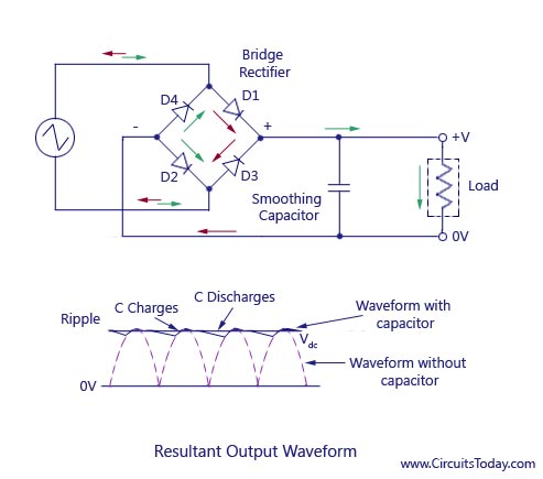
I will put a capacitor on the rectifier output, but probably also a resistor first, to limit the inrush current when it's first powered up.  A discharged cap looks like a dead short to DC.  There's probably enough bulk resistance in the rectifier to do the job, but why take chances?

So, DCC, track-powered, remotely dimmed, warm-white LED strip lights.  This will work standing still, in reverse, etc.

One final point: the color.  According to John H. White, Jr., in his 1977 article on Pintsch lights in Technology and Culture, the light was "an intense, slightly blue-green flame."  I'm thinking a cool white might be the best match for this.  Pintsch gas lights were the dominant lighting source for the period of these cars, 1888 to 1928 or so. 
#25
Joe is right, the rectifier should be marked with two terminals for AC input, and then a plus and minus DC output.  Here's one I bought for this purpose:


The inner two terminals are the AC inputs; no polarity, naturally. 

The wiring is as follows:


The textual way of describing a circuit is to name the nodes and the terminal of the components and associate them.  If we name nodes left to right, top to bottom you have node1 being the connection between D2 and D4, which includes the bottom of the capacitor and the bottom of the load, and can be considered the DC ground, or "0V" node.  Let's call positive of an electrolytic cap terminal 1, and the anode of a diode node 1, and for the ambiguous components the topmost terminal(or otherwise leftmost terminal) in the schematic as node 1.  This yields:

node1: D4.1 D2.2 C1.2 Load.2
node2: AC.1 D4.2 D1.1
node3: AC.2 D2.2 D3.1
node4: D1.2 D3.2 C1.1 Load.1

After all that, you might want to consider a resistor between the rectifier and the cap, since a discharged cap looks like a dead short circuit for a short time, until it accumulates some charge  The bigger the cap, the longer this condition persists.  This could exceed the rectifier's current handling capacity, and burn it out.  I kinda doubt that, though, as there is probably enough bulk resistance in the rectifier diodes to limit the inrush current sufficiently.  (That said, there might be sufficient bulk capacitance in the LED's to make the discrete cap unnecessary).

The circuit for this would be:

node1: D4.1 D2.2 C1.2 Load.2
node2: AC.1 D4.2 D1.1
node3: AC.2 D2.2 D3.1
node4: D1.2 D3.2 R1.1
node5: R1.2 C1.1 Load.1

I'm curious, what components and values were recommended?

Thanks,

jv
#26
Quote from: charon on April 24, 2015, 09:21:41 PM
Yea!
Goodbye JVSS!
Chuck
I didn't say I was going anywhere!  :)

Seriously, just really interested in what was actually done, what color and how bright coach lights should be, and so on.

I'm going to model mine as having Pintsch gas lights. 
#27
OK, Kevin, so if you're saying the EBT used the headlight dynamo to light passenger coaches during its passenger era, i.e., not during its present era as an "attraction," I will accept that.
#28
Kevin, granted most of what I know about this topic comes from White's "The American Railroad Passenger Car," and various internet sources, but I don't think I misread, and I beg to differ with your view on this.  "Head end" refers to the lead car in a train, and was a term of art before electrical power was generated in the head end car.  Head end cars were usually baggage, or post office, or some combination including passenger/baggage combines.  Head end power for electrical lights was commonly axle-driven dynamos, or steam, either reciprocating steam engines or steam turbines driving dynamos.  Internal combustion engines for head end power were rare.  I have never, in any reading I've done so far, seen mention of a locomotive headlight dynamo used to light passenger cars, nor ever heard that referred to, or included in descriptions of head-end power. 
#29
Federal law required electric headlights in 1915.  So, I assume that most narrow gauge railways only electrified in response to that regulation. 

BTW, the way I read your comment was that head end power meant 110V AC - I don't think that's the case. My guess is that HEP for lighting would have been DC.

Few people seem to know that many places, even in our lifetime, used DC power for lights and ventilation in buildings, etc.

(My grandfather was the chief engineer for Fordham Hospital in the Bronx, where all of the electricity was generated with two steam engines, and the steam plant also supplied the heat.  Lights were DC.  Incandescent bulbs don't care, nor do universal motors).

#30
They will work with Bachmann steel switches?