I mentioned in my layout thread a while back that I was starting on a Shay project. Well, here it is....
While perusing the web one day, I came across a site detailing the different types of geared steam locomotives. On the page covering the Willamettes, I found the following picture of a design that was apparently on Willamette's drawing boards when they went out of business. A two-truck, 6-axle locomotive.
http://www.mrollins.com/willam.html
Thinking what an interesting model this would make, I immediately started wondering what it would take to turn a Bachmann Shay into this never-built locomotive. Some initial studying and measuring of the Bachmann model lead to the conclusion that it was feasible, but I decided that since this isn't really a prototypical locomotive, I would save some headache and not try to turn the Shay into a Willamette. Building the proper cylinder bank and valve gear didn't seem very appealing.
My original plan was to turn this into a "Pacific Coast" –style Shay with the all-weather cab, girder frame, and cast trucks. After much thought, I decided I didn't want to tackle trying to scratch-build the cast truck side-frames. This decision lead to the next decision that making the frame and cab modifications would be pointless without the cast truck frames. I decided I would only worry about necessary changes to fit the 3-axle trucks, leaving the factory truss-rod frame, boiler, and cab. Modifications needed would be the front and rear pilots and water tank / fuel bunker. Maybe in the future I'll come up with a way to make the cast truck side-frames, and then make the other modifications.
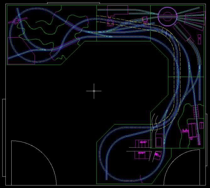
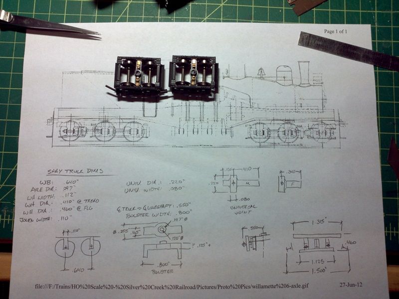
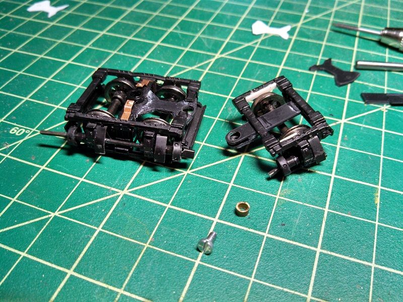
The physical part of the project started with extra front and middle Shay trucks that I had in my workbench drawer. I began disassembling them and taking measurements of all the components. I then started drawing the components in AutoCAD to determine how certain components were going to fit together and what would need to be modified. For simplicity sake and compactness, I decided to not model the truck equalizer bolster as seen in the Willamette design. Instead, I would utilize two factory middle trucks and graft on an articulating 3rd axle and frame cut from the other trucks. I worked out the pivot point and designed the needed parts for the articulating 3rd axle in CAD.
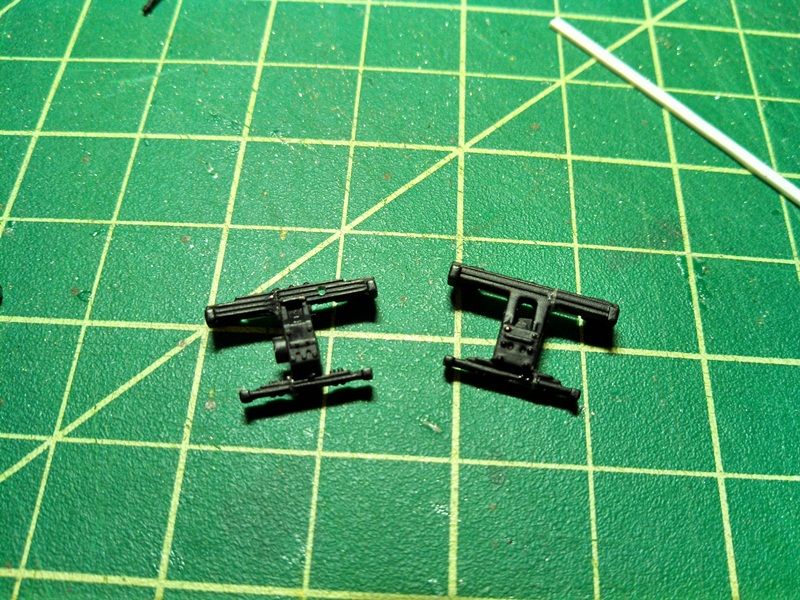
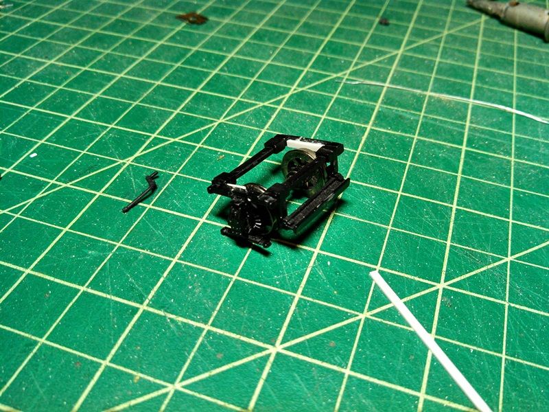
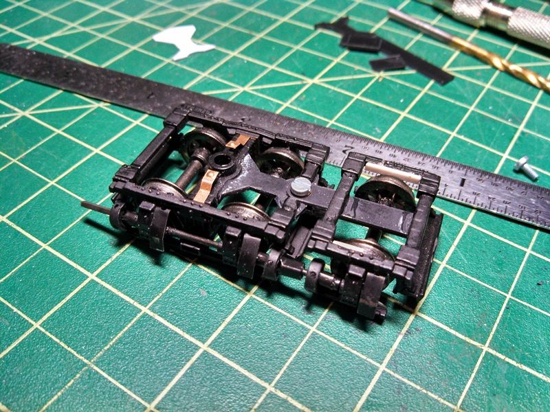
With design work done, I began by modifying the extra trucks. Only minor trimming needed to be done to the middle truck. The front truck saw considerable cutting and splicing of the side-frames to form the single-axle unit. Next, pivot parts were cut from styrene and a bushing from brass tubing, then the parts were glued (with CA) to the appropriate truck component. Holes were drilled (and tapped) after the glue had dried. Lineshafts were reassembled with NWSL gears and one of the original slip-joints cut down to the appropriate length to go between the 2nd and 3rd axles. This makes up the front 3-axle truck.
I didn't want to spend money on another Shay until I was surer this truck was going to work. So, with the first truck done and appearing to function as expected, I was confident enough to make a purchase. During the planning and design process, I had been keeping an eye out on eBay for a suitable Shay. After a few months of watching, I was lucky enough to score the particular model I was looking for at an acceptable price, an undecorated steel cab model.
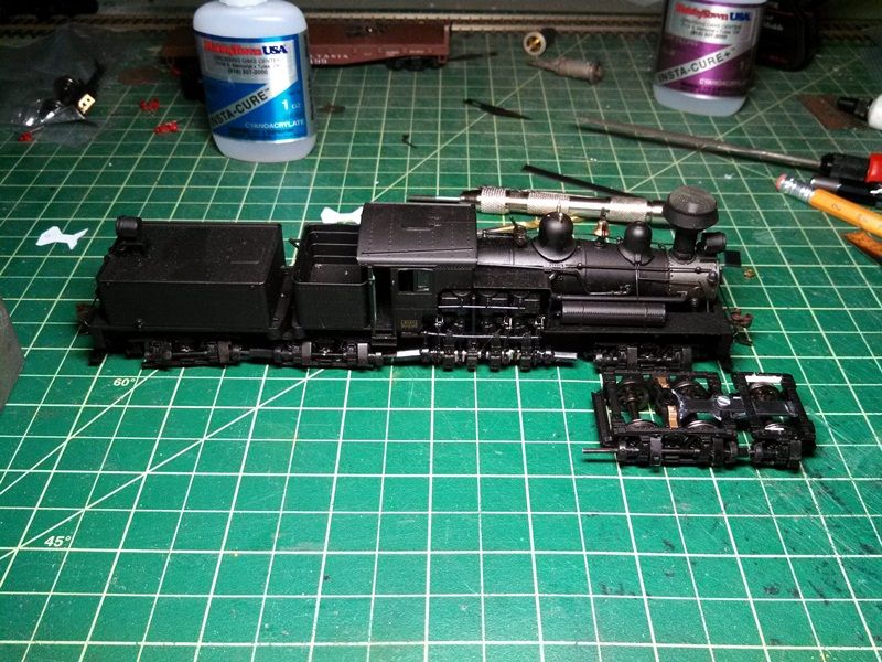
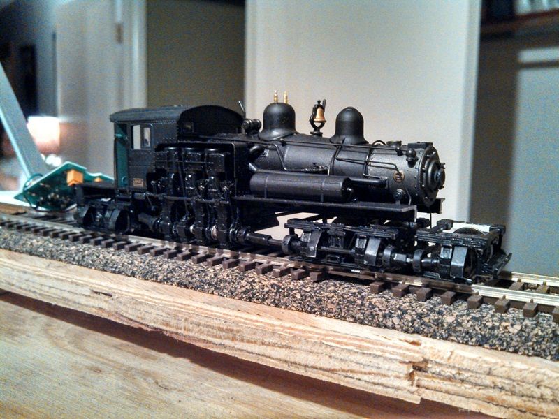
Before any serious or irreversible damage was done to the new Shay, I wanted to test the first trucks operation under its own power before proceeding any further. This meant disassembling most of the locomotive and removal of the front pilot for the new truck to fit. Testing went well. Only issue that arose was that the shortened slip-joint would come apart while negotiating left-hand curves. The truck would want to articulate instead of rotating in relation to the frame. I solved this by adding a travel limiter to the 3rd axle frame. I also added some weight to the 3rd axle frame to help it track a bit better.
As seen in the pictures the front pilot will need to be extended forward about 7/8" to clear the 3rd axle. I may look into the possibility of moving the front bolster rearward to reduce the amount needed to extend the pilot.
Currently, work is beginning on the rear truck. Once it is complete, will move on to extending the front and rear pilots and figuring out what to do with the water tank & coal bunker.
More to follow.....
While perusing the web one day, I came across a site detailing the different types of geared steam locomotives. On the page covering the Willamettes, I found the following picture of a design that was apparently on Willamette's drawing boards when they went out of business. A two-truck, 6-axle locomotive.
http://www.mrollins.com/willam.html
Thinking what an interesting model this would make, I immediately started wondering what it would take to turn a Bachmann Shay into this never-built locomotive. Some initial studying and measuring of the Bachmann model lead to the conclusion that it was feasible, but I decided that since this isn't really a prototypical locomotive, I would save some headache and not try to turn the Shay into a Willamette. Building the proper cylinder bank and valve gear didn't seem very appealing.
My original plan was to turn this into a "Pacific Coast" –style Shay with the all-weather cab, girder frame, and cast trucks. After much thought, I decided I didn't want to tackle trying to scratch-build the cast truck side-frames. This decision lead to the next decision that making the frame and cab modifications would be pointless without the cast truck frames. I decided I would only worry about necessary changes to fit the 3-axle trucks, leaving the factory truss-rod frame, boiler, and cab. Modifications needed would be the front and rear pilots and water tank / fuel bunker. Maybe in the future I'll come up with a way to make the cast truck side-frames, and then make the other modifications.
The physical part of the project started with extra front and middle Shay trucks that I had in my workbench drawer. I began disassembling them and taking measurements of all the components. I then started drawing the components in AutoCAD to determine how certain components were going to fit together and what would need to be modified. For simplicity sake and compactness, I decided to not model the truck equalizer bolster as seen in the Willamette design. Instead, I would utilize two factory middle trucks and graft on an articulating 3rd axle and frame cut from the other trucks. I worked out the pivot point and designed the needed parts for the articulating 3rd axle in CAD.
With design work done, I began by modifying the extra trucks. Only minor trimming needed to be done to the middle truck. The front truck saw considerable cutting and splicing of the side-frames to form the single-axle unit. Next, pivot parts were cut from styrene and a bushing from brass tubing, then the parts were glued (with CA) to the appropriate truck component. Holes were drilled (and tapped) after the glue had dried. Lineshafts were reassembled with NWSL gears and one of the original slip-joints cut down to the appropriate length to go between the 2nd and 3rd axles. This makes up the front 3-axle truck.
I didn't want to spend money on another Shay until I was surer this truck was going to work. So, with the first truck done and appearing to function as expected, I was confident enough to make a purchase. During the planning and design process, I had been keeping an eye out on eBay for a suitable Shay. After a few months of watching, I was lucky enough to score the particular model I was looking for at an acceptable price, an undecorated steel cab model.
Before any serious or irreversible damage was done to the new Shay, I wanted to test the first trucks operation under its own power before proceeding any further. This meant disassembling most of the locomotive and removal of the front pilot for the new truck to fit. Testing went well. Only issue that arose was that the shortened slip-joint would come apart while negotiating left-hand curves. The truck would want to articulate instead of rotating in relation to the frame. I solved this by adding a travel limiter to the 3rd axle frame. I also added some weight to the 3rd axle frame to help it track a bit better.
As seen in the pictures the front pilot will need to be extended forward about 7/8" to clear the 3rd axle. I may look into the possibility of moving the front bolster rearward to reduce the amount needed to extend the pilot.
Currently, work is beginning on the rear truck. Once it is complete, will move on to extending the front and rear pilots and figuring out what to do with the water tank & coal bunker.
More to follow.....