Awesome! Thank you for taking the time to verify that, Yardmaster! Tell your service guys thanks as well! Also, do you know at what amperage the 5A power booster trips at? I'm planning to use DCC Specialties' PSX-1s to provide further protection. Are PSX-1s compatible with the Bachmann 5A power booster? Thanks again!
- Welcome to Bachmann Online Forum.
News:
Please read the Forum Code of Conduct >>Click Here <<
This section allows you to view all posts made by this member. Note that you can only see posts made in areas you currently have access to.
Pages1
#1
General Discussion / Re: How to connect Dynamis + ProBox + 5A power booster?
March 04, 2017, 10:15:45 PM #2
General Discussion / Re: How to connect Dynamis + ProBox + 5A power booster?
March 04, 2017, 06:17:17 PM
Oh, duh! Thanks!
#3
General Discussion / Re: How to connect Dynamis + ProBox + 5A power booster?
March 04, 2017, 05:04:09 PM
I received my Dynamis command station and ProBox yesterday. I'll get my power booster on Monday (March 6, 2017), so hopefully I'll see a reply here from someone from Bachmann by then. Here's a better photo of the back of the command station and ProBox:
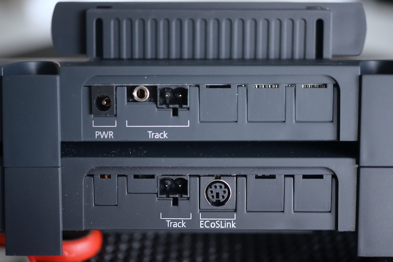
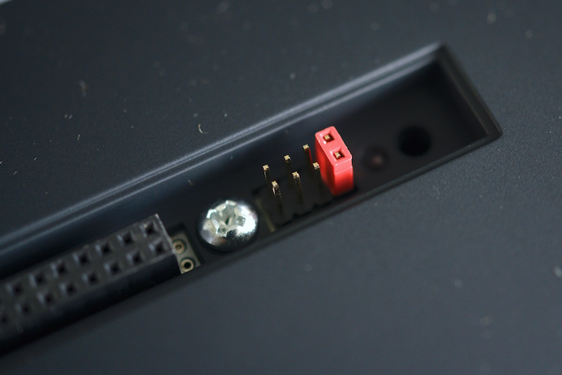
I also have one more question: Shown below, I installed the jumper on the ProBox in the "system 1" position (the default, with no jumper is "system 0"). I plan to buy a second Dynamis command station, but not a second ProBox. Will setting this jumper on this ProBox allow me to use the second Dynamis command station in the same room?
This confusion arises because there's no way to set a "system number" on a Dynamis command station alone (without a ProBox), which I'm assuming will behave as "system 0," even without a ProBox attached. Is this correct?
#4
General Discussion / How to connect Dynamis + ProBox + 5A power booster?
March 02, 2017, 10:30:38 PM
I just purchased a Bachmann Dynamis (US version), ProBox, and Bachmann 5A power booster. However, nowhere in the Bachmann documentation does it explicitly tell you how to connect the power booster if you have a Dynamis mounted on a ProBox (the Bachmann power booster user manual never even mentions the ProBox). Here's how I believe you're supposed to connect the Dynamis command station, ProBox, and 5A power booster:
[NOTE: BACHMANN HAS CONFIRMED THAT THE DRAWING IS CORRECT.]
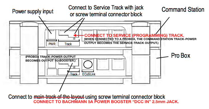
Main-track 5A power booster hook-up:
ProBox TRACK POWER --> power booster DCC IN --> power booster POWER OUT --> MAIN TRACK
Cable required: 2.5mm sub-mini plug-to-bare wire: [this cable is now provided.]
tip: unused
ring = positive (red)
sleeve = negative (black)
1. Attach the two bare wires to the green screw-terminal connector block on the ProBox --> TRACK POWER output.
2. Connect positive (red) wire to left terminal-screw. Connect negative (black) wire to right terminal-screw.
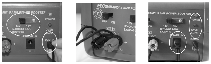
3. Insert the other end of the cable, the 2.5mm sub-mini plug, into the power booster --> DCC IN jack.
4. Connect bus wire to large POWER OUT screw-terminals on the power booster and connect to the MAIN TRACK.
Service-track (low-voltage) power hook-up:
Dynamis command station TRACK POWER --> SERVICE TRACK
Cable required: 3.5mm (1/8") mini plug-to-bare wire: [this cable is now provided.]
A. Create an electrically isolated track section using insulated joiners on both rails to use as a short service track (programming track).
B. Insert the 3.5mm mini-plug (1/8") into the Dynamis command station --> TRACK POWER output jack (which, when attached to a ProBox, is actually now the service-track output). [Alternatively, you can also just connect bare wires to the Dynamis command station --> TRACK POWER screw-terminal connector block.]
C. Attach the two bare wires on the other end of the cable to the SERVICE TRACK, observing correct polarity (e.g., RED = right rail; BLACK = left rail).
Questions:
• Are the procedures as described above all correct?
• At what amperage (i.e, when a short occurs) does the power booster trigger a power-off system shut-down?
[NOTE: BACHMANN HAS CONFIRMED THAT THE DRAWING IS CORRECT.]
Main-track 5A power booster hook-up:
ProBox TRACK POWER --> power booster DCC IN --> power booster POWER OUT --> MAIN TRACK
Cable required: 2.5mm sub-mini plug-to-bare wire: [this cable is now provided.]
tip: unused
ring = positive (red)
sleeve = negative (black)
1. Attach the two bare wires to the green screw-terminal connector block on the ProBox --> TRACK POWER output.
2. Connect positive (red) wire to left terminal-screw. Connect negative (black) wire to right terminal-screw.
3. Insert the other end of the cable, the 2.5mm sub-mini plug, into the power booster --> DCC IN jack.
4. Connect bus wire to large POWER OUT screw-terminals on the power booster and connect to the MAIN TRACK.
Service-track (low-voltage) power hook-up:
Dynamis command station TRACK POWER --> SERVICE TRACK
Cable required: 3.5mm (1/8") mini plug-to-bare wire: [this cable is now provided.]
A. Create an electrically isolated track section using insulated joiners on both rails to use as a short service track (programming track).
B. Insert the 3.5mm mini-plug (1/8") into the Dynamis command station --> TRACK POWER output jack (which, when attached to a ProBox, is actually now the service-track output). [Alternatively, you can also just connect bare wires to the Dynamis command station --> TRACK POWER screw-terminal connector block.]
C. Attach the two bare wires on the other end of the cable to the SERVICE TRACK, observing correct polarity (e.g., RED = right rail; BLACK = left rail).
Questions:
• Are the procedures as described above all correct?
• At what amperage (i.e, when a short occurs) does the power booster trigger a power-off system shut-down?
Pages1